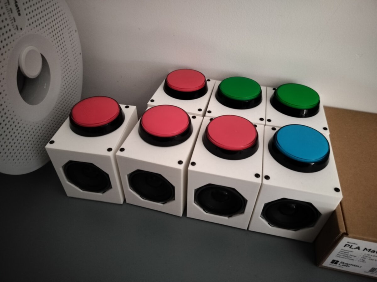
Configurable sound box
The reason I even though of doing this project was because of a joke.
We live in a world where information is incredibly available. So much so that much of it is consumed under the form of internet memes. Wether these are images, videos, or sounds, memes are everywhere and reflect people's emotional perception of the world. I often find myself in situations that remind me of one. I guess I'm drawn to them because I don't like to take things seriously. Life is more fun if you add humour to things.
So I thought, why not make a sound box that plays memes? And why not make it configurable so that I can add new ones whenever I want?
And that's how this project was born.
Check it out on github!
Features
The button has the following features:
- 3MB of storage for multiple small mp3 files.
- Incredibly easy to use thanks to DNS redirection.
- Ability to easily add and remove files wirelessly.
- 7 second upload time for 500kB files.
- Volume adjustment and gain adjustable.
- Powered over USB-C.
- Cool illuminated massive arcade button.
- Custom 3D printed case.
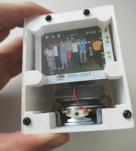
- Transparent base with an image
on the back of the PCB thanks to JLCPCB.
Hardware architecture
To be honest, aside from choosing roughly the right components in hardware, I just winged it feature wise. I just started with the basic functionality I wanted, and then added more features as I went along.
Choosing the controller
I'd already come across some projects on the internet that used a MCU from Espressif Systems for audio projects. I already had some ESP8266 boards, and since I wanted to make the box configurable, I thought it would be a great choice since ESP specifically designed their chips to have Wi-Fi capabilities.
The ESP8266 fulfills these requirements:
✅ It is Configurable
✅ It can play sound
So that was how I chose the controller.Choosing the amplifier IC
Of course I knew that MCU's
can't provide enough current to drive a speaker,
since most of them are roughly limited to 50mA.
At first I looked into the different classes of amplifiers and quickly figured out
class D amplifiers were the way to go.
Despite this, I definitely want to look into more analog amplifiers in the future
like class A, B or AB (But that's for another project).
I mainly saw two different amplifier IC's that people used :
If you look at each of their datasheets, you'll notice that they are not driven the same way. One is with an analog signal (PAM8403) and the other digitally (MAX98357A). You can imagine I was quite confused seeing people drive the PAM8403 since the ESP8266 has no DAC.How where people driving it then?
Of course now the answer seems obvious:
It is driven using the same tricks as a class D amplifier.
The MCU
approximates an analog signal by
switching the output on and off at a high frequency.
It is modifying the pulse width of the signal to increase or decrease the average voltage.
And that average voltage represents the analog signal.
All that is needed is a low pass filter to smooth out the signal.
And if the PWM frequency is high enough,
the speaker can actually act as that LP filter.
This particular application of PWM
is referred to as delta-sigma modulation.
I even remember trying the demo program that plays a wav file inlined in the binary. I was so baffled at it working!
So after understanding how we can simulate a DAC using PWM and some clever FW, I decided to go with the simpler option and drive an amplifier with simple I2S. This seemed like a more elegant option since the ESP8266 has a built-in I2S peripheral, and is likely a better choice rather than simulating a DAC.
As far as the amplifier IC goes, I went with the MAX98357A since I had no other specific requirements. And you can find this IC used pretty much everywhere.
Breakout board or nah?
In order to learn a little soldering and save some PCB footprint, I decided against using a breakout for the amp IC. A decision I may have regretted later on.
First revision
For the first revision I used some random footprint of an ESP8266 board I found on the internet.
They look the same, so it must be the same footprint.
- I thought...
...I thought wrong.
The pin number was the same but the separation between the male headers was just far enough to make me have to bend the pins of the dev board and push with more force than I was comfortable with. The board worked fine otherwise.
My idea though was to make several of these buttons. But the issue is I was relying on the 5v from USB to power the amplifier. And in order to do so, it had to be routed to the VIN pin. Except it was not... On most of the extra dev boards I bought. So I had to make a second revision of the board.
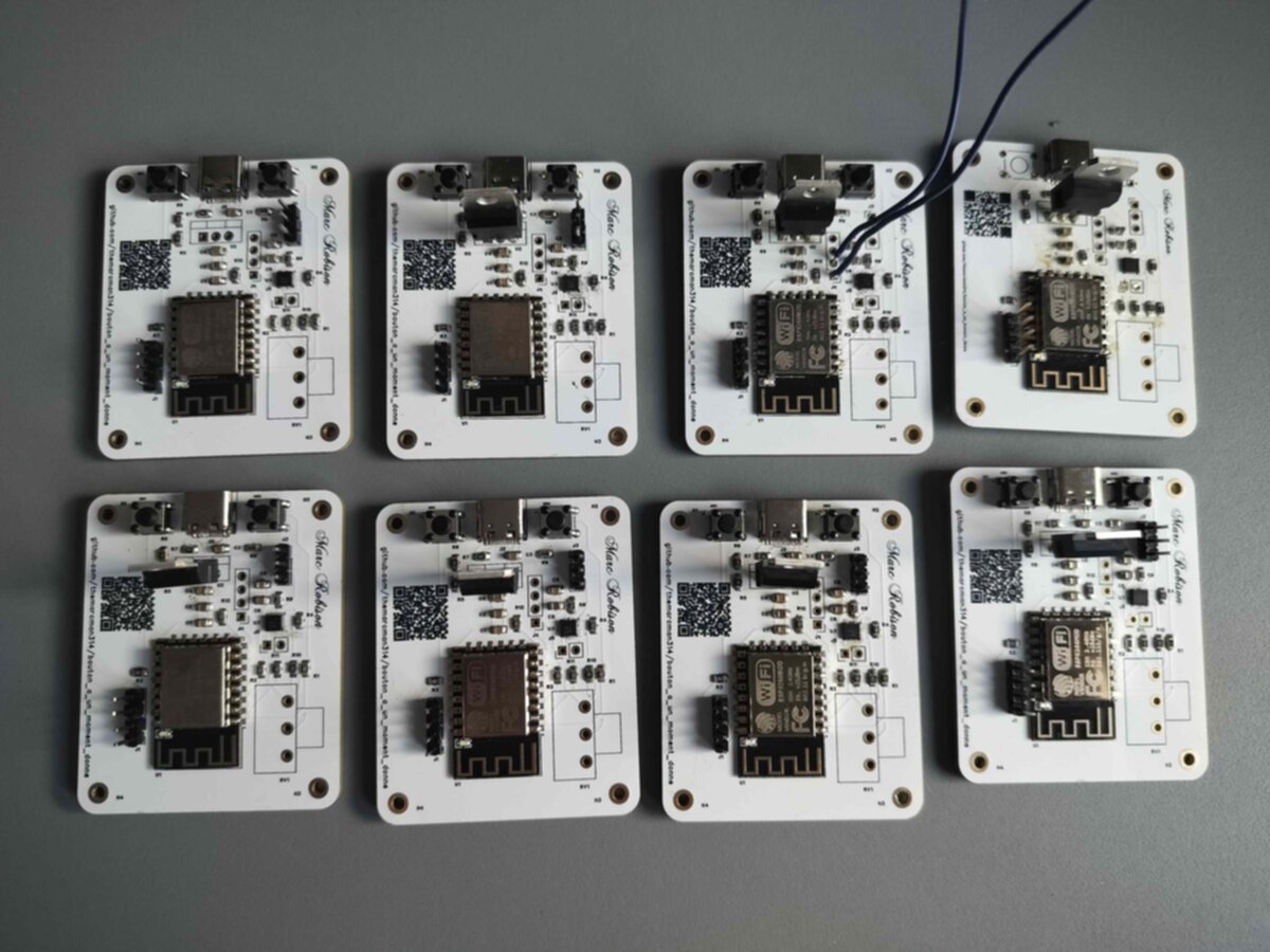
Module wiring
For this revision I decided:
Why don't I create my own dev board?
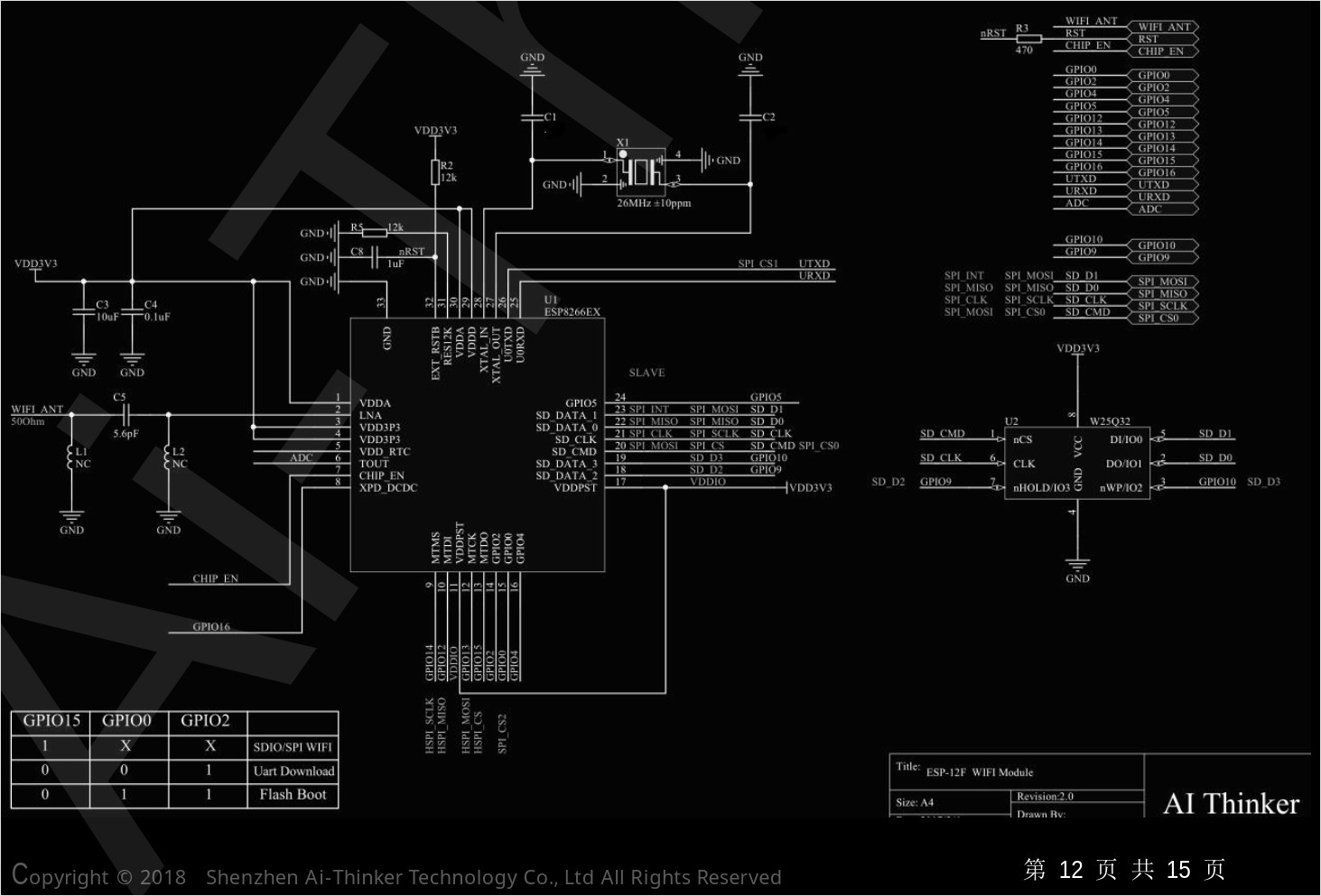
Well I did not have much of a choice anyway unless I could find dev boards that consistently had 5v at VIN like I expected. So I simply used the ESP12-E/F modules from aliexpress. I first looked up the module's datasheet to figure out what resistors I had to add.
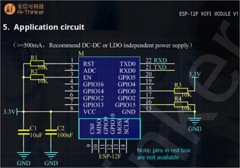
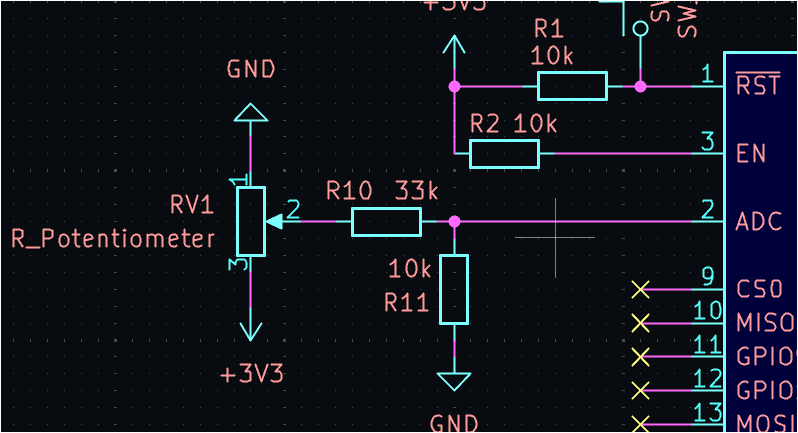
Yes, the ESP8266 modules require external resistors to work properly.
Again using their datasheet I figured out the appropriate logical for booting
in read or write to SPI flash.
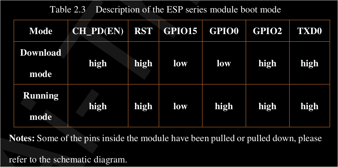 As you can see, the GPIO0 pin has to be pulled low in order to download a new program.
Or pulled high to boot normally.
In order to switch between the two modes I simply added a button like so:
As you can see, the GPIO0 pin has to be pulled low in order to download a new program.
Or pulled high to boot normally.
In order to switch between the two modes I simply added a button like so:
GPIO0 is pulled high by default, and when the button is pressed it is pulled low. So whenever I want to upload a new program, I simply hold the button down while powering the board. Otherwise the basic resistor configuration is the same as the application circuit given by AI-Thinker above.
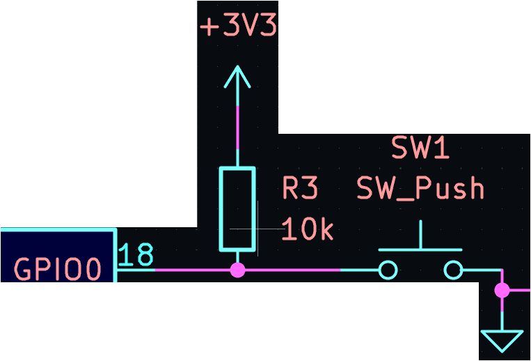
Surrounding the controller I decided to add:
- A potentiometer for SF volume control.
- Another input with a pull up resistor in order to play the memes (huge arcade button).
- USB-C receptacle for powering the board
- LM317 for dropping the voltage
- A pin header for programming
- A pin header for configurable gain of the amplifier.
Potentiometer
For the potentiometer I am simply reading a scaled down (/3) version of the cursor pin. Since yes the controller's ADC takes a maximum of 1.0V.
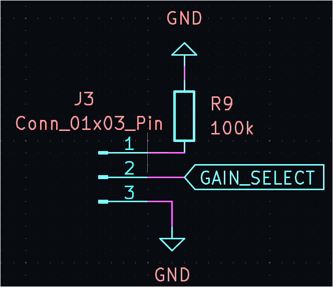
Configurable gain
I decided to add a configurable gain for the amplifier as a way for the user to choose between louder or better quality sound.
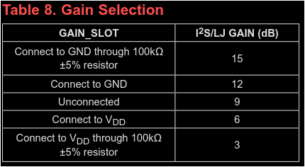
The following configuration allows for the user to choose between 9, 12, or 15dB, depending on the jumper position.
USB-C
As for USB-C, the spec requires a way to indicate that a device is plugged in. This is only the case for C to C cables because without an indication as to which device is the host and which is the peripheral, the host would not know whether to provide power or not. It would not be a good idea to connect two powered hosts together, and that's why USB-C does not initially provide power. It instead relies on resistors connected to the CC pins to indicate that the device is a peripheral and should be powered. Additionally, I was not in need of more than 15W of power, and that is why I did not implement USB-C PD.
This is the configuration I used for my USB port:
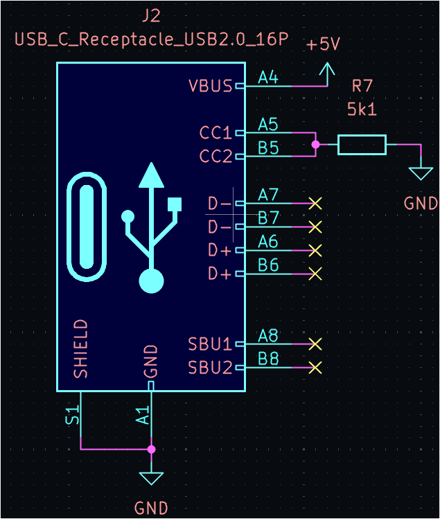
But I should've instead used two separate 5.1k resistors Rd like so:
It somehow still worked as you can see in the image bellow, I get the expected voltage from the single resistor to ground. My design however does not comply with the USB-C spec. And I should have used two resistors to ground instead of one.
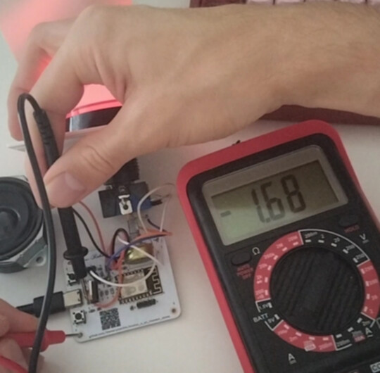
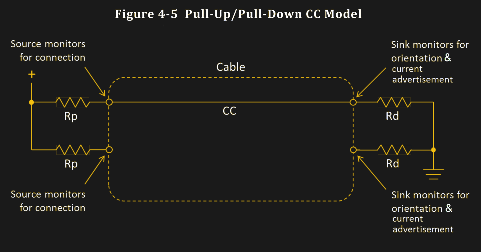
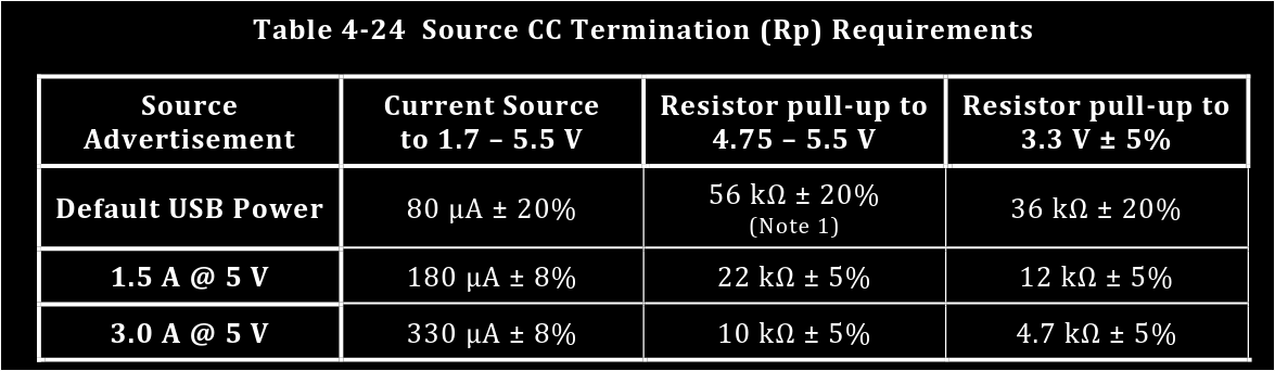
To confirm this we can simply check the table of expected voltages
for the USB-C CC resistors in the USB-C spec, or calculate it ourselves.
In order to calculate it ourselves, we first need to lookup the appropriate resistor
value for the corresponding pull-up voltage.
Let us assume our charger uses 5V and therefore 10k Rp resistor.
For a 5.1k resistor, the expected voltage is therefore:
\[V_{CC} = 5 \times \frac{5.1k}{5.1k + 10k} = 1.689V.\] Our calculated voltage matches our 1.68V measurement.
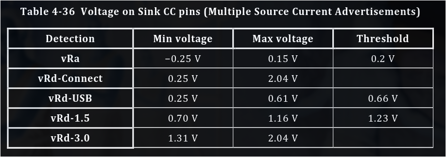 This does in fact confirm that up to 15W (5V@3A) can be provided to the device.
To learn more about this, take a look at:
All About
USB-C: Resistors And Emarkers
or The
official USB-C spec
Voltage regulation
As for the LM317, I needed a way to drop the voltage for the ESP8266 module. So I used an LM317 to drop the voltage to 3.3V. The first batch of boards with one provider of LM317 came out fine, but the second batch with another provider did not work. After measuring the output voltage of the regulator at around 1.6V I then realized that I simply was not giving enough margin for the regulator to operate. You see, the LM317 recommends a minimum of 3V between the input and output voltage. And since I was powering the board with 5V, 1.7V was not cutting it.
If we look at the dropout voltage chart from the datasheet we get a much clearer picture:
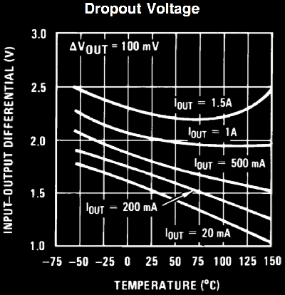
As you can see, the dropout voltage is not constant, but rather depends on the output current as well as temperature. If we assume 200mA of current consumed by the ESP8266, we can see that 1.7V is right at the limit of working properly. I even tried to lower the output voltage to 3.0V by changing the resistors to allow for a larger margin, but that did not work either. This goes to show that low dropout regulators are such a better choice for this range.
Basic firmware overview
If you've made it this far congrats!
Now let's quickly go over the firmware.
The firmware is written in C++ using the Arduino framework.
The libraries used are ESP8266WiFi, ESP8266WebServer,
DNSServer, ESP8266TimerInterrupt, and finally ESP8266Audio.
Storing and playing the files
This is the library that does cool stuff like emulate a delta-sigma DAC for analog amplifiers. But in this case we are just using AudioGeneratorMP3 class to play mp3 files over the I2S interface using the AudioOutputI2S class. The files are stored in a SPIFFS file system on the 4MB SPI memory (AudioFileSourceSPIFFS class).
WAP
My goal was to make it as simple as possible to add new files. So I configured the ESP8266 as a WAP so that people could just connect to it instead of having to connect it to their home network.
Web server
I also added a web server to allow users to upload files and configure what file they currently want to play. The song currently selected for playback stored in a text file for persistence. The site is written practically only in HTML and CSS, it uses a little bit of JavaScript to handle error messages for file names. I even implemented a CSS animation for page loading and during file uploads.DNS server
In order to simplify users experience, I also added a DNS server to allow users to access the web server automatically. Yes, I created a captive portal that redirects users to the web server when they connect to the WAP.Firmware Volume control
As for the volume control, I simply read the potentiometer value every 100ms
or so in a timer ISR, scale it down to a value between 0 and 1
and then use the AudioOutputI2S::SetGain() function to set the volume.
What I learned
- Use a LDO regulator or switching converter for tight regulation like this one.
- Measure your components and PCB footprint before ordering them.
- Use two 5.1k resistors instead of one for USB-C sink advertising.
- Order a stencil if working with no lead packages like TQFN lol.
- Double check the strength of pull-up/pull-down resistors needed in the case of modules/SIP